
In principal, the ICs implement a capacitance multiplier circuit to emulate the Y-capacitors in a conventional passive filter design.
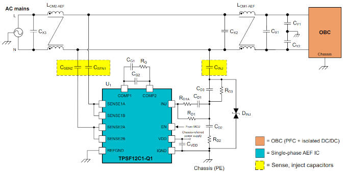
They do while sitting amongst smaller filter inductors and capacitors (see diagrams) while summing the high-frequency components of the voltages from the two or four ac power conductors, and then injecting an anti-phase ac current derived from these signals back into the neutral.
“The effective active capacitance is set by the circuit gain and the injection capacitance,” according to TI. “The active EMC filter sensing and injection impedances use relatively low capacitance values with small component
footprints.”
Electronics Weekly note (and we are trying to confirm this, or otherwise, with TI. Watch this space).
TIs literature mentions injecting current into the neutral line a great deal, but not, it appears to Electronics Weekly, that the ground terminal (and Vdd+decoupling) of the IC is doing the bulk of the work. The IC’s ground is connected to EMC ground, and common-mode EMC energy is dumped through here, just as it would be with normal Y-capacitors – but the gain in the circuit decreases the necessary capacitor size.
The Y-capacitors in a passive design are replaced by the gain plus CINJ (see diagram) and a path through the existing X-capacitors – in effect, the IC and its circuit have converted some of the common-mode noise into differential noise that can be dealt with by the X-capacitors. In a neutral-less three phase system, CINJ would need to be replaced with a star of three capacitors.
please help out by commenting below if you see holes in this thinking before TI gets back to EW. End note.
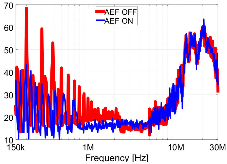 What ever the mechanism, the result, said TI, is a low impedance path for common-mode noise enabling “15 to 25dB of CM noise reduction over, for example, 150kHz to 3MHz, helping to reduce the size of common-mode chokes”. It also said: “as much as 30dB at between 100kHz and 3MHz” and that they are capable of “helping to meet CISPR 25 Class 5 EMI limits for conducted and radiated emissions”.
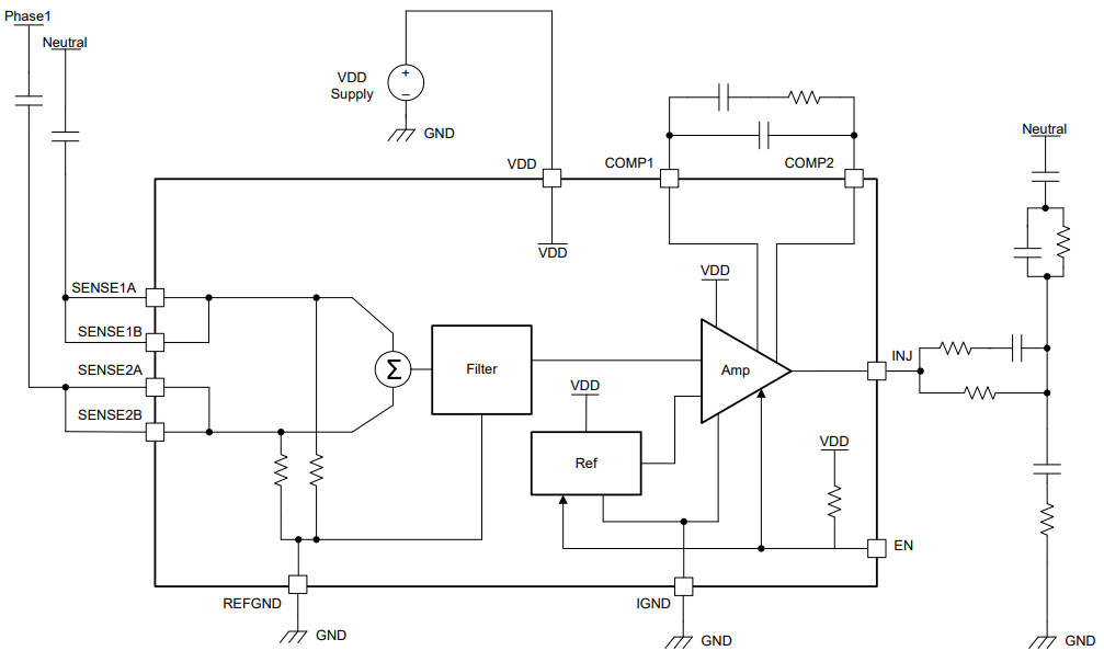 The difference between single and three phase versions is only the number of inputs provided to sense voltages – two or four respectively (diagram right), the three-phase version has four input load resistors). All of these signals are summed internally into a single ac signal, which is filtered appropriately.
The sense and injection capacitors (see diagrams) have to be Y-rated components.
The other passive components on the output are for damping – to manage resonance between the still-needed common-mode choke inductance and the injection capacitance – which appear in the active loop gain as a pair of complex zeros.
There are four devices: TPSF12C1 and TPSF12C3 for single- and three-phase commercial applications, then TPSF12C1-Q1 and TPSF12C3-Q1 for automotive use. Volume production is scheduled for the second quarter of 2023, with additional active EMI filter ICs appearing later this year.
Operation is over 8 to 16V (18V withstood) and up 105°C ambient (150°C junction).
Protections include under-voltage lock-out, and thermal shut-down, and there is an enable pad.
They “meet IEC 61000-4-5 surge immunity requirements, minimising the need for external protection components such as transient voltage suppression diodes”, said TI.
Packaging is 4.2 x 3.3mm 14pad SOT-23
Applications are foreseen in on-board chargers, servers and uninterruptable power supplies.
This application note has the clearest information about these ICs and includes an example of inductor size reduction