
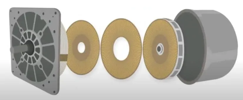
“The rotors and stators are made from standard PCBs and have an optimised set of conductive metal traces that radiate out from the centre hub on the plates,” according to the company, which claims its technology is scalable to multi-megawatt outputs.
The PCBs are stacked with rotor and stator plates alternating.
There are dozens, or even hundreds, of radial copper lines on the PCBs – shaped like long thin triangles.
The stator drive is three-phase, with every third copper radial fed by the same phase. [Ed, this makes it far from electrostatic, but we are running out of language here…]
On the rotor PCBs, in one version of an electrostatic motor, every second copper radial is positively biased, and those in between are negatively biased. other arrangements can have single or multi-phase ac rotors as well as multi-phase ac stators.
 With the correct relative numbers of segments on the rotor and stator PCBs, applying the three-phase stator voltage causes the rotor to produce torque and to spin itself to a speed dependent on the supply frequency.
As there are so many segments, rotational speed is much lower than the drive frequency, leading the company to pitch its electrostatic motors against gearbox-equipped standard motors.
Drag between the rotating and static discs caused by the dielectric liquid that the motor has to be filled with also discourages high-speed operation – the company has discussed a maximum around 500rpm.
This liquid has to be there for two main reasons:
- To prevent arcing across the sub millimeter disc-to-disc gap from the thousands of volts needed to generate significant torque.
- To increase torque through a high dielectric constant.
According to the company, the liquid needs a breakdown strength of at least 5kV/mm, preferably 10kV/mm, and a dielectric constant of at least three, preferably above seven.
Secondary aims are: low viscosity to reduce drag, low conductivity to block current leakage, and sufficient thermal capacity to carry heat away.
C-Motive is keeping its dielectric liquid formula a secret, but an example of such a liquid can be found in patent attributed to Daniel Ludois (C-Motive founder), Daniel Klingenberg and Kevin Frankforter (C-Motive test scientist): liquid isoamyl isovalerate into which barium titanate nano-particles are suspended to increase dielectric constant.
No details of the multi-kV multi-kHz drive electronics have been revealed, although the advent of silicon carbide mosfets has potentially simplified such designs.
Two motor example shave been published: One around 250mm in diameter producing at least 1.5kW of power or ~30Nm of torque, and another around 500mm in diameter rated somewhere up to 20kW and 400Nm.
The company is keen to point out the lack of rare-earth metals in its designs, and low I2R losses – the latter particularly if asked to hold a static position where <0.2% loss compared to full drive power is claimed.
Potential applications, according to C-Motive, are driving: fans, conveyor belts, pumps, compressors and mixers.