

ST’s BMS demo with EIS
In addition to cost, range anxiety and fast-charging capability, the safety of Li-ion batteries (LIBs) is an important factor when considering an electric vehicle (EV). Practical application use cases of electrochemical impedance spectroscopy (EIS) can further complement the current battery management system (BMS) data-driven algorithms, enabling better use of the existing LIB by fully understanding its limits. Such sensor fusion data, coupled with physical, machine learning and AI algorithms, can further accelerate the acceptance of EVs without compromising battery health and safety.
Accuracy and monitoring
Transport electrification is taking place at an increasingly rapid pace, enabling significant steps towards decarbonisation. Essential to this transition have been the development and constant innovation of LIBs that power most EVs. Despite the environmental benefits of this transition, dependence on LIBs poses significant challenges, with end-user concerns including range anxiety, fear of battery failure and charging time. Easing these concerns requires the ability to accurately monitor and forecast battery performance, on top of innovations in cell chemistries, system architectures and charging algorithms.
The battery management system is one such key element that helps monitor critical battery parameters for the safe and efficient operation of the EV battery. Figure 1 provides a top-level overview of a BMS with some of its key components. One of its main functions is to ensure that every Li-ion cell within the battery pack functions in its safe operating area (SOA), as operation outside the SOA can lead to severe consequences, including thermal runaway.
Thermal runaway in Li-ion batteries
Despite the nominal SOA that is defined over a statistical population of batteries, each cell within the pack operates under a different mission profile, depending on the vehicle and/or the driving/charging profile. The different stress applied to the cells can lead to a scenario in which each cell’s internal state, including the extent of lithium plating or electrode cracking, can vary significantly, both at an intra-pack and inter-pack level. Hence, accurate estimation of battery performance and prediction of battery failures require a non-invasive method to gather information about the cell’s state at a microscale, complementing the already available battery parameters.
Thermal runaway is a violent chain reaction of exothermic chemical reactions resulting in an uncontrollable increase in system temperature. This in turn can lead to a propagation phenomenon which, if not controlled, leads to a battery fire.
In Li-ion batteries thermal runaway can be caused by mechanical damage, external heat, short circuit or overcharging. Thermal runaway is characterised by very rapid progress and it can result in a battery fire or even an explosion, eventually leading to the self-destruction of the battery.
EIS principle
EIS is a powerful technique to characterise electrochemical systems, such as Li-ion cells. EIS captures the response of the cell over a broad frequency range, with different frequencies correlating to distinct physical, chemical and mechanical changes in the active material. The fundamental approach requires a small AC current (excitation signal) flowing through the Li-ion cell and consequently measuring its AC voltage response. From the AC current and the measured AC voltage response, the impedance of the Li-ion cell can be determined.
The first potential application use case of EIS in EVs is early Li-ion cell thermal runaway prediction.
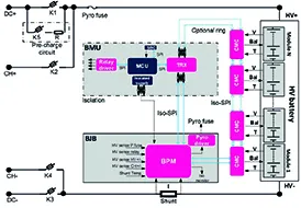
Figure 1: Overview of a BMS with its key components
As per the GB 38031-2020 standard (effective from January 2021) for all EVs to be sold in China, five minutes before a danger is caused in the passenger compartment due to thermal propagation, as a result of thermal runaway of a single battery, the battery pack or system shall provide a thermal event warning signal.
Monitoring the cell temperature is crucial for LIB safety and durability. Placing a temperature sensor on every cell in a battery pack is not a feasible solution. Moreover, temperature sensors are usually mounted on the cell’s surface, thus providing only an indirect measurement of the inner junction temperature. EIS could enable achieving the same without using internal or external hardware. This could result in an increased understanding of the cell’s SOA, leading to enhanced usability of each cell within the pack. Therefore, more efficient usage of the cell’s energy might even allow reaching the same driving range, but with potentially fewer cells within the pack. Additionally, this could optimise the system cost by requiring fewer temperature sensors.
Improved fast charging
Another use case relates to charging. Very often cell suppliers set strict safety margins within which a Li-ion cell has to operate. This can restrict the system from delivering the best possible performance, especially while charging an xEV (that is, EVs and variants).
EIS provides a fair indication of a Li-ion cell’s state parameters and depending on the status of the cell the fast-charging profile can be adapted while at a charging station.
In real-world applications, potential EIS implementation propositions could include, but are not limited to, the following:
* Central excitation and central measurement: The battery pack is excited with a central current source, such as a traction inverter. The excitation current and the corresponding voltage drop could be measured by the cell monitoring chip and the current sensor. The MCU then calculates the impedance using the voltage and current. This approach has the advantage of reusing the already available sensor data by adapting the algorithms, but it might be limited to specific driving modes.
* Local excitation and local measurement: Every individual cell module within the pack is excited using local excitation circuitry. The corresponding voltage drop can be measured by the analogue front-ends and the impedance is locally calculated on-chip.
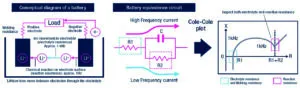
Figure 2: LIB schematic, its equivalent circuit and Nyquist curve
On one hand, this approach on one side can save the communication bus load on an MCU, but on the other side may come at a higher cost since it requires additional components to modulate the excitation current and balance heat dissipation.
Proposed EIS implementation
To measure battery impedance, two components are necessary: an excitation system to stimulate the battery and an acquisition system to acquire cell voltage and current synchronously. The collected data is processed by dedicated MCUs working as a BMS entity, covering BMS functions to balance performance, robustness and cost with advanced EIS-based diagnostics.
About The Author
Akshay Misra is technical marketing, BMS, STMicroelectronics. Contributions from Filippo Bonaccorso and Kaushik Salver, both STMicroelectronics