
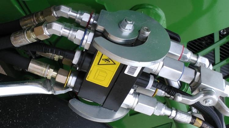
 Figure 1: Troubleshooting involves performing a diagnosis of the fluid power system and then outlining the course of action that will restore the machine back to its normal operation.
A hydraulic system is a fluid power system that performs work using pressurized fluids. However, just like in every other system, faults and problems are bound to arise in fluid power systems. For instance, engineers are sometimes plagued with challenges related to pressure, flow, leakage and vibration.
Each of these problems can be caused by several factors. And the first step engineers must take to solve the problem is to troubleshoot the hydraulic system. Troubleshooting involves performing a diagnosis of the fluid power system before outlining the course of action that will restore the machine back to its normal operation.
The steps for troubleshooting hydraulic systems are highlighted below.
No. 1: Inspect the system and check the factory manual
The first step is to inspect the fluid power system. During this phase, engineers want to check the factory manual and service history of the system and compare the system’s current performance with previous records. For instance, by checking the system’s normal operating temperature in the factory manual, engineers will quickly determine if the machine is running hot.
Other essential things engineers should inspect are the fluid’s condition, pump, housing, valves, strainers, filters, electrical controls and pipes. Once these components have been inspected, engineers should proceed to list the symptoms that were observed. For instance, here is a list of possible symptoms an engineer could notice:
- Machine runs hot
- Pressure fluctuates
- Leakage in the pipe
- Low system pressure
- The hydraulic cylinder moves too slow
Each of these symptoms can be caused by several problems. Therefore, the next step would be to find the possible problems using the symptoms.
No. 2: Find the problem
Most of the symptoms observed after inspecting a hydraulic system can be grouped into either of the following problems:
- Flow problems
- Pressure problems
- Leakage problems
- Noise and vibration problems
- Heat problems
For instance, consider the symptom of “the hydraulic cylinder moves too slow.” In this scenario, the general problem is related to flow, and it could be caused by several factors. The goal is to list these possible factors. For instance, the possible factors causing the hydraulic cylinder to move slowly include:
- Restriction in the filter and pressure lines
- High oil viscosity
- Air leakage in the suction line
- Pumps running too slow
- Low pressure
- High pressure
- Badly worn pumps, valves and cylinders
Notice how the possible factors are listed in the order of easiest to most difficult to test. For instance, engineers can easily test for restrictions in filter and pressure lines by simply inspecting the pressure drop across the filter. Also, engineers can test for “high oil viscosity” and “air leakage” in the suction through inspection, while a strobe light tachometer can be used to check for “pumps running too slow.” Performing tests in order of easiest to most difficult ensures that engineers do not waste time (and resources) tearing down the machine when there’s absolutely no need for it.
No. 3: Perform basic calculations
If after simple tests have been performed, and the actual problem has not been determined, engineers can proceed to perform basic calculations before breaking connections to perform tests on the system. For instance, the cause of the “low pressure,” “high pressure” and “badly worn pump” problems might be in the hydraulic cylinder or pump. In such a scenario, engineers might want to perform basic pressure calculations to establish what the expected pressures should be.
Essential calculations for hydraulic systems include:
Pressure in the cylinder
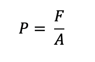 Hydraulic cylinder pressure equation.
Where:
F = force on the piston (lbf)
A = piston area (in2)
Motor torque
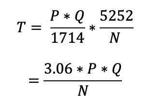 Hydraulic motor torque equation.
Where:
T = torque (lbf-ft)
P = pressure (lbf/in2)
Q = flow rate (gal/min)
N = motor speed (rpm or revolutions per minute)
Flow rate for extending and retracting cylinder
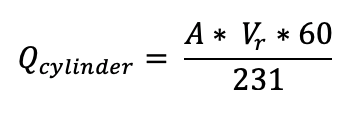 Flow rate for hydraulic extension and retraction equation.
Where:
A = cylinder area
Vr = cylinder rod velocity
Flow rate for a rotating pump
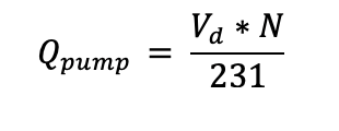 Flow rate equation for hydraulic pump.
Where:
Vd = pump displacement (in3/rev)
N = pump speed (rpm)
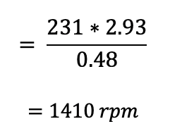
For instance, consider a scenario where there is a need to determine the expected speed of a hydraulic motor with a displacement of 0.48 in3/rev. Suppose the hydraulic pump used to drive the motor has a displacement of 0.7 in3/rev and rotates at 1,100 rpm. If the internal leakage through the system was accounted to be 0.4 gal/min, then the expected speed of the motor will be 1,410 rpm, as shown below:
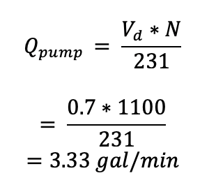
This is the theoretical flow from the hydraulic pump. The actual flow from the pump can be calculated by subtracting the internal leakages, as shown below:
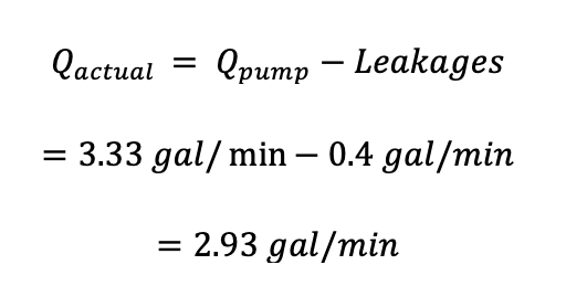
Therefore, the actual speed of the motor will be obtained as 1410 rpm, as shown below:
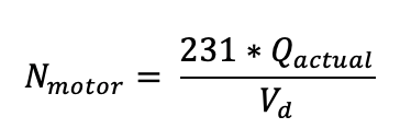
Where:
Vd = motor displacement
Conclusion
Troubleshooting hydraulic systems can be quite challenging and time-consuming. But engineers must always resist the urge to find a quick fix to any problem the system might be experiencing. Instead, they want to perform a proper diagnosis of the fluid power system.
[Learn more about hydraulic equipment and components on GlobalSpec.com.]