
Calculating the Resonant Frequency of an LC Circuit
When an inductor and capacitor are connected in series or parallel, they will exhibit resonance when the absolute value of their reactances is equal in magnitude.
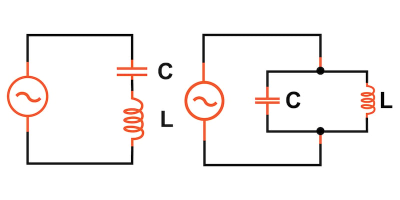
Series and parallel LC circuits
The reactances or the inductor and capacitor are given by:
$$X_L = 2 pi f L$$
$$X_C = frac{1}{(2 pi f C)}$$
Where:
- XL = inductor reactance
- XC = capacitor reactance
- L = inductance in H
- C = capacitance in F
- f = resonant frequency in Hz
Setting XL = XC and solving for the resonant frequency results in the following equation:
$$f = frac{1}{(2pisqrt{LC})}$$
Alternatively, if we have a target resonant frequency and know either the inductance or capacitance, we can solve for the other required component value:
$$L = (frac{1}{C}) · (frac{1}{(2 pi f)})^2$$
and
$$C = (frac{1}{L}) · (frac{1}{(2 pi f)})^2$$
Applications
The resonant effect of LC circuits has many important applications in analog and RF signal processing including use in notch filters, bandpass filters, and oscillators.