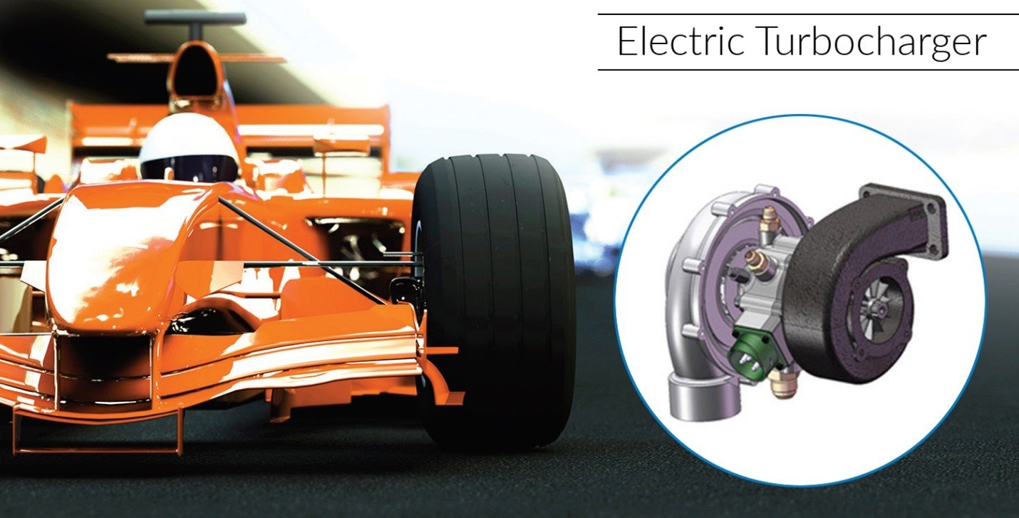
 Figure 1: An electric turbocharger. Source: Arnold Magnetic Technologies
As the automotive industry continues to move toward more energy-efficient systems, new technologies are emerging. Innovations such as thermal energy recovery systems and electrically assisted turbochargers use permanent magnet motors and generators in order to improve vehicle efficiencies. These technologies are being used in the Formula One racing circuit and are making their way into the commercial automotive landscape.
What is an electric turbocharger?
As engines downsize toward 1.0 L, 1.5 L and 2.0 L, forced induction becomes an increasingly vital component to maintaining high power outputs similar to traditional 2.5 L to 3.5 L V6 engines. The smaller engine displacements do not typically provide enough exhaust gas flow at lower RPMs to make effective use of the turbocharger. An electrically assisted turbocharger, or e-turbo, is similar to the traditional turbocharger system that uses exhaust gas flow for “boost,” except that it is designed with an integral high-speed electric motor. This additional motor helps to achieve boost at lower RPMs to improve both launch and transient performance. The electric motor can drive the compressor at the lower engine RPMs while the engine spools up to higher RPMs where it can provide enough exhaust flow for “normal” turbocharger operation.
Electric motor design considerations
Surface mounted permanent magnet (SMPM) topology offers advantages such as the highest torque/inertia ratio, simple construction, the highest torque density, good torque control, very low rotor losses and common drive topology.
Permanent magnet (PM) motors for e-turbo applications have additional design challenges including high centrifugal force on permanent magnets, high eddy currents and rotor losses introduced if electrically conductive, sleeve material, which is used to retain the permanent magnets, cooling of sleeve and magnets, trade-off between price, size and quality of permanent magnet material, and risk of demagnetization of permanent magnets.
As electric motors become smaller and faster, designers must consider the potential effects such as electrical drive frequencies, magnetic eddy currents, laminated steel eddy currents, mechanical stresses on the faster rotating shaft (rotor dynamics), and electrical control of the motor through the inverter.
Electrical and magnetic phenomena that create excess heat within the motor during operation include the “skin effect” in the copper windings, which increases at higher speeds as switching frequencies increase. It also includes hysteresis losses occurring within the stator lamination stack and rotor eddy current losses, which are dependent on the material used for the retention band on the PM rotor. To compensate for the extra heat, it is best to design with materials that perform under high temperature conditions or materials that help reduce the amount of heat generated, or both.
Performance materials enabling energy efficiency
Arnold Magnetic Technologies’ performance materials help balance these design challenges, allowing motors to function in extreme conditions while at the same time helping to increase their overall efficiencies.
RECOMA samarium cobalt
Driven by the smaller, faster, hotter requirements in emerging motor technology, Arnold Magnetic Technologies offers highly dense, sintered magnet materials that provide increased magnetic performance at elevated temperatures. Arnold now produces a 33MGOe SmCo material, RECOMA 33E, which is considered to be the best performing SmCo material on the market today. RECOMA 33E allows for the greatest power density at elevated temperatures when compared to existing commercial magnetic materials. The performance comparison shown uses an N40UH neodymium iron boron magnetic material, which has a high level of dysprosium, an extremely scarce and expensive rare Earth element.
Arnon thin film lamination steel
One of the primary methods to reduce the number of eddy currents induced in the lamination stack assembly is to use thinner cross-sectional material. The thinner material restricts the current to much smaller paths as opposed to solid stator cores. By taking a core and constructing the length from hundreds of thinner laminations that are electrically insulated, the normal magnetic flux paths are greatly restricted. Another way to reduce eddy currents is by using a very high resistivity steel. The motor designer might assume that increasing R would only increase the eddy current as it is defined as i2R losses. In reality, the amount of current (i) that will flow normal to the desired flux path is reduced, creating less eddy current. This is traditionally done by using a high silicon content steel (0.5wt% to 3.5wt%).
Arnold’s precision thin metals (PTM) division manufactures precision rolled thin (0.060 inches to 0.0005 inches or 1.524 mm to 0.013 mm) and ultra-thin (0.00049 inches to 0.000069 inches or 0.01245 mm to 0.00175 mm) gauge metal strip and foil products from a wide range of permanent and soft magnetic materials as well as non-magnetic alloys. These precision thin materials allow motor designers to push their high-speed motor designs to the limit by enabling the reduction of eddy currents. Other services provided by PTM include heat treating, surface cleaning, slitting and special coating.
For the complete article, including charts and illustrations, visit the Arnold website.