
Zone triggering allows users to specify trigger conditions by drawing one or more zone areas on the instrument’s display.
Each acquisition is then inspected for these conditions, and displayed if it meets them. Otherwise it is discarded.
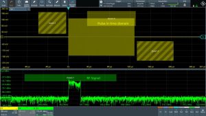
Zone triggering on a specific RF chirp length in the time domain, and when the chirp exceeds a certain power level in the frequency domain.
“Zone triggering can be very effective for triggering on non-monotonic edges, serial bus patterns, math waveforms, events across multiple channels and events in the frequency domain. For these use cases traditional oscilloscope triggers simply do not work,” according to the company. It “enhances the oscilloscopes’ ability to precisely isolate events that are difficult or impossible to detect with traditional oscilloscope triggers”.
The asic, called MXO-EP, was first included in R&S’ MXO 4 oscilloscopes in 2022, followed by pairs of them in MXO 5 (2023) and MXO 5C (2024) scopes. It can process at 200Gbit/s and update at over 4.5 million acquisitions/s. Triggering is possible on events of less than 0.0001 vertical division, with user-selected hysteresis.
Zone triggering is among functions that were included in asic’s hardware, for which software is now being provided – in this case in the free update to firmware version 2.2. “The ASIC is coming closer to leveraging its full potential with the new firmware, with more features in the pipeline,” R&S told Electronics Weekly.
Users can define up to four zones by drawing on the touch display over input channel waveforms, maths waveforms (including power analysis waveforms) and frequency spectra.
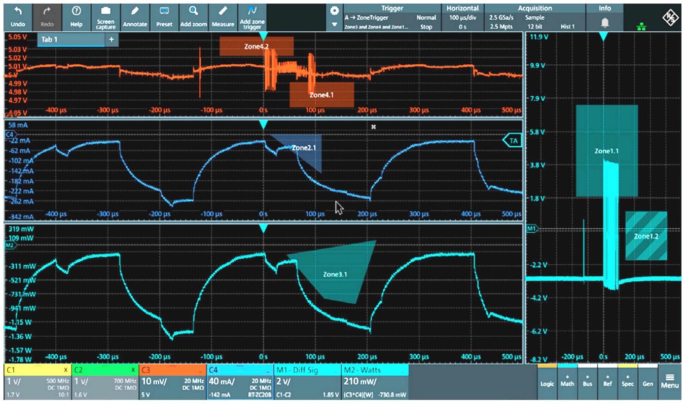 Each zone can have up to eight areas, with areas defines as polygons with up to 16 points.
Triggering can be on areas intersecting, or areas not intersecting. The relation of zones to cause a trigger can be defined by Boolean expressions. Zone trigger ca be combined with edge, glitch, width, runt, window, timeout, interval, slew rate and other forms of trigger.
“Users testing and debugging in the frequency domain using an oscilloscope can now draw specific zone areas. The oscilloscope will then trigger or activate when a certain tone exceeds a set power level within these zones,” said R&S. “Or users can simply draw a zone for RF chirps or pulses. New, is free run mode, where the oscilloscope captures as fast as possible without looking for an edge trigger event. Combining this with zone triggering can be very effective for power integrity measurements and EMI debug.”
Electronics Weekly thanks R&S for its lightening-fast responses to questions, which were used to improve an earlier version of this article.